How Do Fiber Optic Security Cables Work to Prevent Theft?
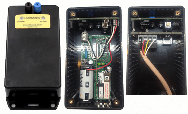
On the left is the LightGard unit; middle shot is of back of unit, configured for wireless operation (cable harness included). At right is the back of the unit when configured for wired operation (circuit board included).
At the heart of the LightGard Fiber Optic Security System is the LightGard unit itself; this unit can be configured for wireless or wired use according to your preference.
How Do Fiber Optic Security Cables Work?
The unit sends a pulse of light though the fiber optic system and checks to see that the pulse was received. If the circuit is broken, the unit sends an alarm to the connected alarm system. This simple explanation of how optical fiber technology works can be applied to numerous devices.
In the example on the right, the unit is shown with the front view first. From the back view, you can see the wireless configuration (wire harness included). On the far right, the wired configuration (circuit board included) is shown. The wireless configuration has room for the door/window transmitter with its own battery pack to lie inside the LightGard unit. In the wireless configuration, when the circuit is broken, the alarm for that transmitter is triggered. In the wired configuration, the unit sends an alarm signal to the alarm system when the circuit is broken.
As an extra security measure, there is a pressure pin on the back of the unit, where it is mounted to a wall or the underside of a desk. If the unit is ever removed, even partially, the circuit is broken, and the alarm is sounded. The Minatronics Fiber Optics Security System can be used to safeguard almost anything that a 1/8″ diameter fiber optic cable can be looped through. The LightGard unit sends micro-pulses of light through the fiber optic cable several times each second. If the circuit is broken, it sends a signal to the alarm system of your choice.
Protecting Equipment
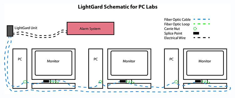
The LightGard unit sends and receives a signal several times a second. The signal passes through the fiber optic cable and all protected equipment. If the circuit is broken, LightGard signals the alarm to sound.
While this technology can be used to protect almost anything, the example on the right demonstrates how to secure computers in a modern high-school or university classroom. You can see in the illustration that there is a fiber optic cable looped through a row of computers, leading to a LightGard unit. PCs are shown here, but LightGard can protect Macs or any type of computer or electronic device.
Please note that the new LightGard WIFI unit does not require a conventional alarm system but uses local WIFI to send a text message to designated mobile phone numbers to instantly notify security personnel, equipment owners or other equipment stakeholders. Read more about LightGard WIFI below.
How Does LightGard WIFI Work?
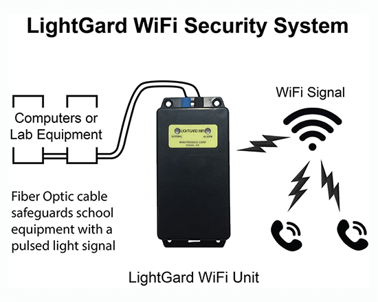 Though the standard Minatronics Fiber Optics Security System requires an alarm system to plug into, the new fully supervised LightGard WIFI unit uses recently patented circuitry and operates completely independently of conventional alarm system control panels and does not even need AC power or a phone line; this amazing unit only requires local WIFI to operate and will send a text to as many mobile phone numbers as you designate if a theft or tamper event is detected! See the schematic at right.
Read more about LightGard WIFI.
Cable Traps
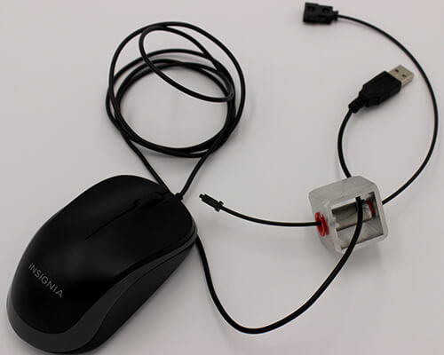
The ‘Mouse Trap’ cable trap can secure USB mice and similarly-sized peripherals.
There are four different sizes of cable traps, which can accommodate and secure cables of different diameters.
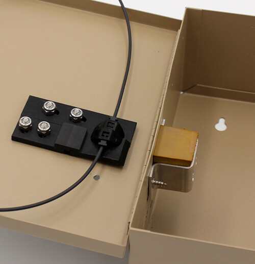
Any device that has a cable or cord can be protected by threading its cable through the open area of cable trap on either side of the cylinder. In the photo on the right, a USB mouse cable has been threaded through a cable trap (the Mouse Trap). Then the fiber cable is threaded through the cylinder after which, as a strain relief, it is affixed with the red washers. The only requirement is that the cable be able to fit in the open area, but both sides of the device should be too big for that particular trap when the cylinder is in place.
The fiber optic cable is threaded through the cylinder in each cable trap. If a thief tries to dislodge the device, they will trigger the alarm. If authorized personnel need to remove the mouse, they can do so by deactivating the alarm and removing the plastic fiber optic cable and cylinder from the cable trap. When complete, they can replace the fiber and reactivate the alarm.
Cable traps can secure computer and electronic components such as mice, keyboards, power strips, fans, heaters – virtually anything that has a cord or cable. These electronics cannot be taken from the cable traps without breaking the circuit, triggering an alarm and alerting authorities. Cable traps obviously do not work for wireless devices.
Securing PCs and Macs
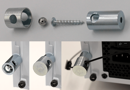
The Carrie Nut can mount to PC frames and disallow access to screw heads.
The Carrie Nut can be screwed into an existing threaded hole in the frame of a PC, either with a sheet metal screw, or a machine screw.
The image on the right shows how the Carrie Nut works; the lower section of the nut is held in place by the screw. A ball bearing covers the head of the screw so it cannot be turned, and the hardened steel cap of the Carrie Nut covers the screw head and ball bearing.
The holes in the lower and upper sections of the Carrie Nut are aligned and fiber optic cable is passed through, holding the two halves of the nut together and making it impossible for thieves to access the screw.
Dislodging the cap will break the circuit, alerting authorities. If authorized personnel need to move or repair the PC, they simply deactivate the alarm, separate the fiber optic cable at the nearest splice point, and remove the screw.
The Carrie Nut can also be used to protect other equipment such as audio, video, or other electronics, as long as that equipment has threaded or non-threaded holes to accommodate the securing screw.
iMacs have an open hole in the support bracket which the fiber optic cable can be threaded through.
Securing a Laptop
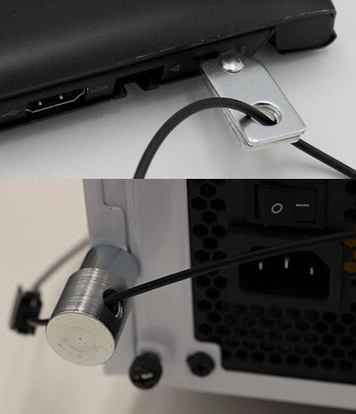
Some of the ways to secure laptops and PCs.
Most laptops come with a 9/32″ Kensington lock slot. When the clip is scissored shut, it cannot be removed. Thread the fiber optic cable through the hole in the Laptop Security Slot Clip, and the laptop cannot be removed unless the fiber optic cable is cut and the circuit is broken, triggering the alarm.
The benefit over a traditional steel cable laptop lock is that when a steel cable lock is cut, there is no alarm. With the LightGard Fiber Optic Security System, an alarm is triggered when the fiber is cut, alerting security personnel. The system even specifies which circuit has been compromised and where that circuit is, increasing the chances of thwarting the thieves in the act.
Splice Points
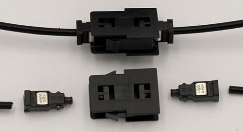
A breakdown of a typical cable splice – two males connect to a double-female.
Splice points can be created by cutting fiber optic cable and attaching a Male MINI-DNP connector to each end; both connectors can fit into a double Female MINI-DNP connector.
In the photo on the right, the top shows two Male MINI-DNP connectors mated to a double Female MINI-DNP connector. The bottom shows the same components, but the fiber has not yet been inserted into the male DNP connectors, nor have the male DNP connectors been inserted into the double Female MINI-DNP connector. This is the simplest type of splice point.
Connecting raw fiber optic cable to the Male MINI-DNP connectors requires use of the LightGard Hot Knife and the LightGard Cut and Melt Tool.
Creating a Splice Point
Splicing together two ends of fiber optic cable is a straightforward process:
- Strip off 1/2″ of coating from end
- Insert newly cut fiber into large end of male DNP connector
- Clamp male DNP connector down
- Insert fiber and DNP connector into large open end of Cut and Melt tool.
- Cut end of fiber off flush with top of Cut and Melt tool.
- Press hotknife against end of fiber exposed through Cut and Melt tool to create a smooth ‘lip’ at end of fiber. Hold in place for approximately 3 seconds.
- Pinch the Cut and Melt tool off of the fiber cable.
- Insert the male DNP connector into a double-female DNP connector.
Securing Access Panels
Equipment panels such as those found on laptops and audio equipment can be secured with Moon Traps – above you can see half of the circuit; the rest of the loop can be attached to the two available female ends shown.
If you have any access panel you’d like to secure, such as a laptop with RAM ports, the Moon Trap can be super-glued to the panel area and the area next to the panel. The cable is threaded through the two halves of the moon trap. In the photo on the right, Moon Traps protect two panels on the back of a laptop. The rest of the fiber optic loop would normally be inserted into the open slots on the left side of each moon trap, completing the circuit.
It is nearly impossible to remove both halves of the Moon Trap at once, and if only one is removed, or if the cable is cut, the circuit is broken, and the alarm is triggered.
Now that you understand how fiber optic security cables work, you can see how easy it is to apply the LightGard Fiber Optic Security System to almost any device. Further examples of Minatronics solutions can be found on the Applications page.