Description
SPECIFICATIONS
Physical:
Molded ABS Black Case
2.45” Wide
1.23” High
5.4” long (w/ mounting flanges)
Mounted with 4 #4 x ½” SMS (included)
Tamper detection on cover removal or unit removal from mounting base using enclosed spring
Power:
10-16 VDC (Hardwired)
3V AA Lithium battery (Wireless)
Features:
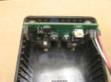
The LightGard III provides fiber loop security detection with the wireless version providing connection outputs to activate popular transmitters made by Ademco, Secure Wireless, DSC, GE/ITI, Napco and Inovonics. The wireless transmitter can be installed within the LightGard III case.
Output:
Hardwired:
Both Normally Open and Normally Closed (NO and NC) dry connections available
Wireless:
Activation/Restore signal for transmitter
LED Displays:
Hardwired:
Red LED:
Displays solid red during tamper alarm condition or when loop is open or bad
Green LED:
Blinks to indicate fiber loop is good.
Note:
The LED’s display status after the loop has been sampled. This scheme removes any loop circumvention from the LED display-loop signal synchronization.
Wireless:
Red LED:
To conserve power, the LED blinks when loop is open or bad or a tamper alarm condition occurs
Green LED:
Blinks to indicate fiber loop is good
Note: Each loop sample is displayed at the same sample rate for a short period of time after a loop status change. The loop display is then sampled to conserve battery power.
Fiber Loop:
Maximum loop length is 400 feet (hardwired) or 400 feet (wireless) with no splices or cable kinks. Subtract approx. 50 feet for each interconnect in the cable.
Modulation pseudo random cable signal patterns
High-Medium-Low Signal Strength selection is available to optimize signal strength for installation loop length. Normally left in High gain mode, the jumper may be placed in a lower gain position to reduce the free-air loop transmission distance on short fiber runs. (see Fig. 1)
Marginal Signal Condition is indicated by both the red and the green LED’s blinking alternately
Mounting:
The control box should be mounted on a flat, non-metallic surface. The tamper spring should be adjusted to allow the tamper switch to be closed when the cover is in place. Secure box to mounting surface using the screws provided.
Wireless:
Fig 3 shows the LightGard III configuration for Wireless operation. The Hardwire interface circuit board must be removed. The 3 conductor cable to transmitter must be attached to the fiber circuit board with the red lead towards the outside of the box. The RED lead metal shim must be inserted between the positive battery terminal and the positive clip in the battery case. The black lead goes to the common lead connection for auxiliary input. The white lead goes to the other auxiliary input lead. NOTE: the battery common connection can usually be verified by a ohmmeter continuity test between the battery minus and the common terminal.
The transmitter should be installed with the transmitter base at the bottom of the box when installed. This will cause the transmitter antenna to be facing upwards. The wire leads should be kept away from the antenna as far as practical.
The installed transmitter box may require a V notch to be put in the side of the plastic transmitter case to allow the wire connections.
The LG III wireless detector can be powered by either a 3.6 volt or 3.0 volt lithium battery transmitter product. It contains a circuit to maintain its internal voltage at 2.8 volts even though the input supply voltage drops to as low as 2.15 volts.
Under normal operation, the battery life is 3-4 years.
BUY NOW


Reviews
There are no reviews yet.